In the circuit shown in the figure (Figure 1) , the capacitors are all initially
ID: 2231897 • Letter: I
Question
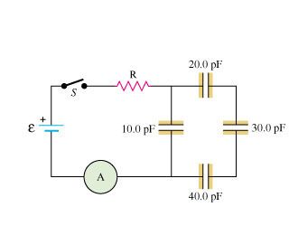
In the circuit shown in the figure (Figure 1) , the capacitors are all initially uncharged and the battery has no appreciable internal resistance. Assume that E= 46.0V and R= 15.0 ohms Here is a link to the figure.
http://i1356.photobucket.com/albums/q730/stackett55/yg_19_69_zpsd2742684.jpg
Part A:
After the switch S is closed, find the maximum charge on each capacitor. q10,q20,q30,q40 in pC
Part B:
After the switch S is closed, find the maximum potential difference across each capacitor. V10,V20,V30,V40
Part C:
After the switch S is closed, find the maximum reading of the ammeter A
Part D:
After the switch S is closed, find the time constant for the circuit in ps.
Explanation / Answer
showing " sorry " please post the figure